Components used:
- Arduino Uno
- 16 x 2 LCD
- 10K potentiometer
- 330Ω resistor
- jumper wires
- breadboard
- type A / type B USB cable connected to PC

Displaying static text:


#include <LiquidCrystal.h>

const int rs = 12, en = 11, d4 = 5, d5 = 4, d6 = 3, d7 = 2 ;
LiquidCrystal lcd(rs, en, d4, d5, d6, d7);

void setup() {
  // put your setup code here, to run once:

  lcd.begin(16,2);

}

void loop() {
  // put your main code here, to run repeatedly:

  lcd.setCursor(0,0);
  lcd.print("   Welcome to");
  lcd.setCursor(0,1);
  lcd.print("Marina Bay Sands");
  delay(500);

}
Pin configurations for 16×2 LCD:
Pin configuration for 16×2 LCD. The above LCD has 16 pins. Their function are:
- Pin 1 – VSS : connection to ground
- Pin 2 – VDD : 5V input
- Pin 3 -V0 : Connected to 10K pot to controlling display contrast for dot matrix(16 dot matrices across x 2 dot matrices topdown). Each dot matrix has 5 columm x 8 row matrix.
- Pin 4 – RS : Register Select. There are 2 modes, low(0) and high(1). Low is to send command and high is to send data.
- Pin 5 – RW : Read and Write. There are 2 modes, low(0) and high(1). Low is Write and high is Read. For this project, we will connect to ground as we are writing only.
- Pin 6 – E :Enable pin. To enable the LCD.
- Pin 7 – D0 : Digital pin. High or low state. Use all 8 pins (8 bits) to display ASCII characters or 4 pins to display numbers and alphabets only.
- Pin 8 – D1 : Digital pin. High or low state. Use all 8 pins (8 bits) to display ASCII characters or 4 pins to display numbers and alphabets only.
- Pin 9 – D2 : Digital pin. High or low state. Use all 8 pins (8 bits) to display ASCII characters or 4 pins to display numbers and alphabets only.
- Pin 10 – D3 : Digital pin. High or low state. Use all 8 pins (8 bits) to display ASCII characters or 4 pins to display numbers and alphabets only.
- Pin 11 – D4 : Digital pin. High or low state. Use all 8 pins (8 bits) to display ASCII characters or 4 pins to display numbers and alphabets only.
- Pin 12 – D5 : Digital pin. High or low state. Use all 8 pins (8 bits) to display ASCII characters or 4 pins to display numbers and alphabets only.
- Pin 13 -D6 : Digital pin. High or low state. Use all 8 pins (8 bits) to display ASCII characters or 4 pins to display numbers and alphabets only.
- Pin 14 -D7 : Digital pin. High or low state. Use all 8 pins (8 bits) to display ASCII characters or 4 pins to display numbers and alphabets only.
- Pin 15 -A : Anode +5V for LCD backlight.
- Pin 16 -K : Cathode Ground for LCD backlight.
————————————————————————————————————-
Displaying moving text with custom character in the 2nd row:
#include <LiquidCrystal.h>
const int rs=12, en=11, d4=5, d5=4, d6=3, d7=2;
LiquidCrystal lcd(rs,en,d4,d5,d6,d7);
char scrolledText[27] = {'W', 'e', 'l','c','o','m', 'e', ' ','t','o',' ', 'M', 'a','r','i','n','a',' ','B','a','y',' ', 'S','a','n','d','s'} ;
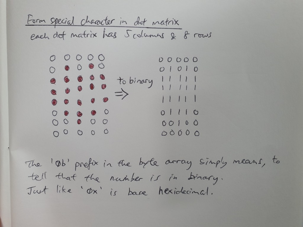
//array for forming the heart shape
byte heartShape[8] = {0b00000, 0b01010, 0b11111, 0b11111, 0b11111, 0b01110, 0b00100, 0b00000};
void setup() {
// put your setup code here, to run once:
lcd.begin(16,2);
lcd.createChar(1, heartShape);
}
void loop() {
// put your main code here, to run repeatedly:
lcd.setCursor(0,0);
for(int i = 0; i<27; i++){
char text = scrolledText[i];
lcd.print(text);
lcd.scrollDisplayLeft();
delay(500);
}
//display 6 times
lcd.setCursor(0,1);
for (int j =0; j<6; j++){
lcd.print("SG");
lcd.write(1);
lcd.print(" ");
}
}