
Just received my MicroChip PicKit4 debugger from RS components.


comes with cable and 2 stickers👍
Memory and features of PIC10F200, 8 bit Flash microcontroller:
| Program Memory(Flash – no. of words) | 256 |
| Data Memory (SRAM – no. of bytes) | 16 |
| I/O | 3 input/output, 1input only |
| TMR0 Timer / Clock (8-bit) | 1 |
| Comparators | 0 |
| Clock | 4MHz |

Learning how to program a microcontroller (‘chip’ in short) indeed takes some time and effort. For PIC 10F200, due to its limited memory, Assembly is a better language. And you will also better understand the inner workings of a computer. Below is my code in Assembly, using Microchip Mplab X IDE version 5.40, with its built in assembler pic-as version 2.20 (Assembly language ‘complier’ is called assembler).
Below 3 images are documents needed which will help you to understand and program the PIC microcontroller PIC10F200. For me it’s a ‘must have’ and can be easily download from the web. I will refer to these documents for my code explanation.
As a lot of web examples are base on MPASM, and the current (July 2020) MPLAB X uses XC8 complier for C language and pic-as assembler for Assembly, this migration guide(bottom pic) will point the difference in keywords used , and the difference in command format. Very useful for me as this project is using pic-as assembler.

Pic A 
Pic B 
Pic C

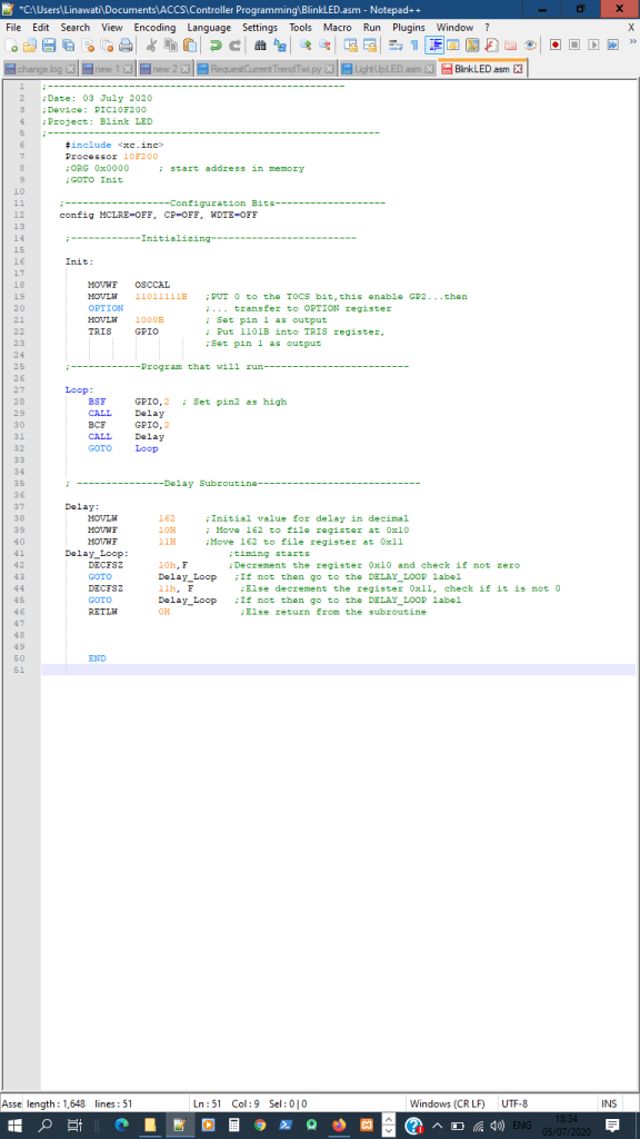
Code explanation for Light up LED program (PIC10F200 SN:30) :
Anything after a semicolon(;) are comments until newline(enter key pressed). Line7: tell the pic-as assembler you are using 10F200 microcontroller. Since this code is just for 10F200 chip/device, the ‘PROCESSOR’ directive should be used.
Line9: to provide the libraries for the assembler, so that certain features of the chip can be used.
- Line11: setting of configuration bits : MCLRE=OFF, CP=OFF, WDTE=OFF MCLR is the Master Clear or Master Clear Reset. In the documentation the MCLR has a overline ( bar on top of the word like this
MCLR)The over line means the MCLR is activated when the pin is pulled low (ie. 0(low) is on and 1(high) is off, in short, active low). Since we off the MCLR (config MCLRE=OFF), nothing more need to be done as we disable it. If its MCLRE=ON, the internal pull up resistor will be on to maintain the pin at a high state(high state meansMCLRis off). - The pull up voltage of Vpp must not be higher than Vdd or else the chip will go the programming mode. Hence to activate the MCLR, a external normally open switch is connected to the pin and ground. So when switch (active low) is close,the pin becomes low(0) and trigger the MCLR reset. When the chip is reset, the program counter will be reset to the top of the memory location (0x00).
- CP is the code protection and WDTE is the watchdog timer, both are configure to OFF. Link for Microchip MCLR : https://microchipdeveloper.com/8bit:mclr
- Line 17: Init: is called label. Labels are just reference points, just in case the program need to loop back to that line. In this section of the code, we are initializing the bits which we will be using.
- Line 19: MOVLW stands for MOVE Literals to Work register and the literals are 11011111B. The ‘B’ stands for binary, this format is only for pic-as assembler. I believe Mpasm uses B’11011111′ format. So the code change the 8 bits in the work register to 11011111.
Below are pictures and videos for this project:

pic 1 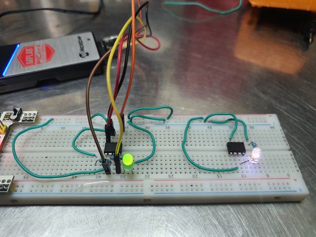
pic 2 
pic 3 
pic 4
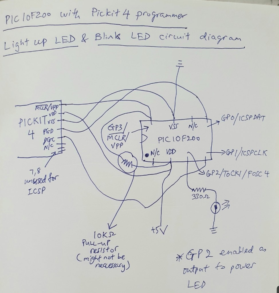
Circuit Diagram for programming chip:
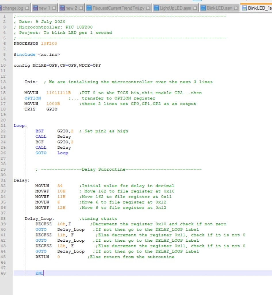
LED with 1 second blinking rate (PIC10F200 SN:27) :
The code is below. The time of 1 second without prescaler is equivalent to 1,000,000 instruction cycles. See below Excel table image for clearer picture. Error on Line 33 and 34 of below code, the comment should be ‘move 34 to file register 0x10’ and ‘move 34 to file register 0x11’ .
| Time(s) | Internal clock (4MHz) | Instruction Cycle clock (4 clicks = 1 cycle) | Instruction Cycle clock (with 256 Prescaler) | comments |
| 1 | 4,000,000 | 1,000,000 | 3906.25 | With 256 prescaler, when tm0 count 3906 cycles, the time is approx. 1 sec |
| 0.5 | 4,000,000 | 500,000 | 1953.125 | With 256 prescaler, when tm0 count 1953 cycles, the time is approx. 0.5 sec |
| 2 | 4,000,000 | 2,000,000 | 7812.5 | With 256 prescaler, when tm0 count 7812 cycles, the time is approx. 2 sec |
| Time(s) | Internal clock (4MHz) | Instruction Cycle clock (4 clicks = 1 cycle) | Instruction Cycle clock (without 256 Prescaler) | comments |
| 1 | 4,000,000 | 1,000,000 | 1,000,000 | No prescaler, when tm0 count 1 million cycles, the time is 1 sec |
| 0.5 | 4,000,000 | 500,000 | 500,000 | No prescaler, when tm0 count 500k cycles, the time is 0.5 sec |
| 2 | 4,000,000 | 2,000,000 | 2,000,000 | No prescaler, when tm0 count 2 million cycles, the time is 2 sec |


Circuit diagram for PIC10F200 microcontroller

PIC10F200 chip used with NPN transistor
