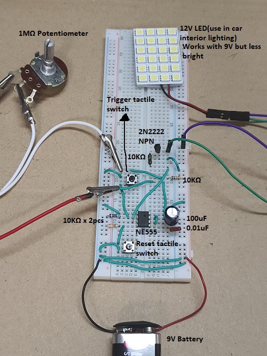
Circuit diagram for connecting LED to NE555 timer, and operating in monostable mode.
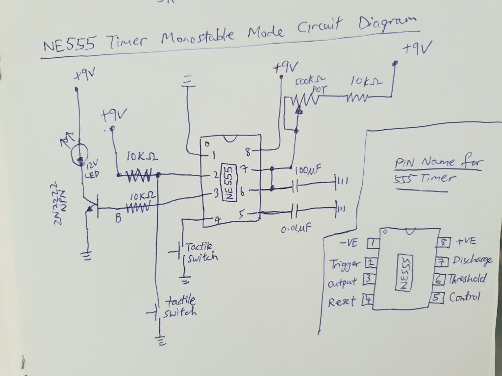
How NE555 timer operate in monostable mode (delay timer):
- Power supply is 5 to 16 VDC (Pin 8) and ground is Pin 1.
- Pin 2 is trigger pin (active low) and always set high by a 10kΩ pull-up resistor.
- Pin 3 is the output pin with max. current output of approximately 200mA, but gets pretty hot at this amount of current. Therefore a 10kΩ resistor to control the current. The 2N2222 NPN BJT transistor will boost the current to light the 12V LED.
- Pin 4 is the reset pin,when pulled low will cause the 555 timer to stop all operations.
- Pin 5 is not in use, and a 0.01uF capacitor is connected to it to prevent pin 5 to be a floating pin.
- Pin 6 and 7 form a RC circuit which determines how long the LED will stay ‘ON’.
- The 1MΩ potentiometer at its minimum will light up the LED for approx. 1 second and at its maximum will light up to LED for 2 minutes.